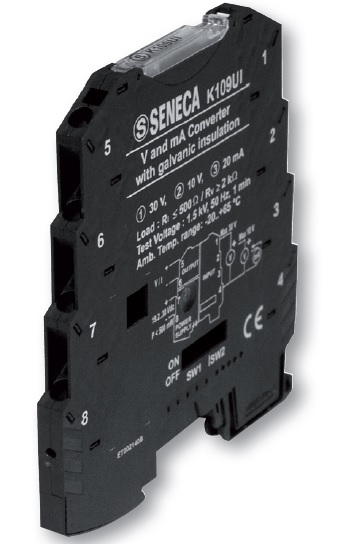
The signal converter or signal conditioner is primarily utilized for data acquisition & process control applications where sensor signals must be normalized and filtered to levels suitable for analog-to-digital conversion so they can be read by computerized devices such as PLC`s & industrial PC`s running SCADA software. Other uses include preprocessing signals in order to reduce computing time, converting ranged data to boolean values, for example when knowing when a sensor has reached certain value.
Types of devices that use signal conditioning include signal filters, instrument amplifiers, sample-and-hold amplifiers, isolation amplifiers, signal isolators, multiplexers, bridge conditioners, analog-to-digital converters, digital-to-analog converters, frequency converters or translators, voltage converters or inverters, frequency-to-voltage converters, voltage-to-frequency converters, current-to-voltage converters, current loop converters, and charge converters.
Despite the continually increasing level of automation equipment capability and the proliferation of fieldbus systems in process automation, signal converters are still indispensible. They essentially perform 3 main tasks:
Signal conversion,galvanic isolation of signalsand the amplification of signals.
In addition, some signal converters can supply 2-wire transmitters. Two distinct systems are available: Passive signal converters designed in the so-called 2-wire technology which obtain their energy directly from the measuring circuit and active signal converter, e.g. isolation amplifiers, which are equipped with a special power supply connection. Galvanic isolation of the individual "circuits" is of great significance. Seneca Z series signal converters typically feature galvanic 3-way isolation which completely decouples the input, output and power supply circuit.
Signal Conversion
An input signal is converted into an output signal. Numerous applications require this feature. For example, resistance or voltage values of temperature sensors are converted into standardised current signals, e.g. 4-20 mA or 0-20 mA. Adaptations from 4-20 mA to 0-20 mA or to voltage signals are also quite common. In addition, input curves often have to be adapted, linearised or inverted. (Figure 3). Signal isolation Input and output signals are galvanically isolated from each other. This avoids parasitic voltages by potential differences, ensures plant safety and protects persons. Galvanic isolation thus safeguards personal security when voltages with dangerously high potentials are measured. Despite the fact that a measuring signal may only amount to a few mV, the potential against earth and thus against persons is dangerously high in case of a failure. This is referred to as the working voltage.
Signal Isolator
Galvanic signal isolator generally describes the electric isolation of two power circuits. Charge carriers cannot flow from one circuit to another since there is no conductive connection between the circuits. However, electric power or signals may be transmitted between the circuits via corresponding coupling elements. A typical example for galvanic isolation is a simple transformer with a primary and secondary winding. Both windings are completely separated from each other. The energy is transmitted by electromagnetic fields. Modern signal converters use a different method for galvanic separation, e.g. optical couplers.
Signal converters with power supply (Active signal converters / 4-wire technology) are equipped with a power supply which is galvanically isolated from the measuring circuit. Depending on the design, these signal converters are frequently not only used as potential isolators but also as signal converters or amplifiers.
Signal converters without power supply (passive signal converters / 2-wire technology) potential isolation or measuring signal conversion does not always demand active signal converters
Signal converters without power supply can be employed frequently without any limitation. In this case, the energy is supplied from the voltage drop at the input terminals of the passive signal converter. However, the appropriateness for the respective application is to be examined taking the power rating of the input signal and the output burden into consideration. Signal converters without power supply do not enable signal amplification and do not work free of reaction, i.e. the output burden bears directly on the input signal.
Signal Amplification
This function is reserved for active signal converters since a separate power supply is needed. Signal amplification performs two important functions: increases the resolution of the inputed signal, and increases its signal-to-noise ratio. For example, the output of an electronic temperature sensor, which is probably in the millivolts range is probably too low for an Analog-to-digital converter (ADC) to process directly. In this case it is necessary to bring the voltage level up to that required by the ADC.
Commonly used amplifiers on signal conditioning include Sample and hold amplifiers, Peak Detectors, Log amplifiers, Antilog amplifiers, Instrumentation amplifiers or programmable gain amplifiers .
4-20mA Current Loops | Signal Conditioner
For industrial process control instruments, signal conditioners with analog 4-20 mA and 10-50 mA current loops are commonly used, with 4 mA representing the lowest end of the range and 20 mA the highest. In a signal conditioner the key advantages of the current loops are that the accuracy of the signal is not affected by voltage drop in the interconnecting wiring, and that the loop can supply operating power to the device. Even if there is significant electrical resistance in the line, the current loop transmitter will maintain the proper current, up to its maximum voltage capability. The live-zero represented by 4 mA allows the receiving instrument to detect some failures of the loop, and also allows transmitter devices to be powered by the same current loop (called two-wire transmitters). Such instruments are used to measure pressure, temperature, flow, pH or other process variables. A current loop can also be used to control a valve positioner or other output actuator. An analog current loop can be converted to a voltage input with a precision resistor. Since input terminals of instruments may have one side of the current loop input tied to the chassis ground (earth), analog isolators may be required when connecting several instruments in series.
Depending on the source of current for the loop, devices may be classified as active (supplying power) or passive (relying on loop power). For example, a chart recorder may provide loop power to a pressure transmitter. The pressure transmitter modulates the current on the loop to send the signal to the strip chart recorder, but does not in itself supply power to the loop and so is passive. (A 4-wire instrument has a power supply input separate from the current loop.) Another loop may contain two passive chart recorders, a passive pressure transmitter, and a 24 V battery. (The battery is the active device).
Panel mount displays and chart recorders are commonly termed 'indicator devices' or 'process monitors'. Several passive indicator devices may be connected in series, but a loop must have only one transmitter device and only one power source (active device).
The relationship between current value and process variable measurement is set by calibration, which assigns different ranges of engineering units to the span between 4 and 20 mA. The mapping between engineering units and current can be inverted, so that 4 mA represents the maximum and 20 mA the minimum.
Signal Converter | Signal Isolator